
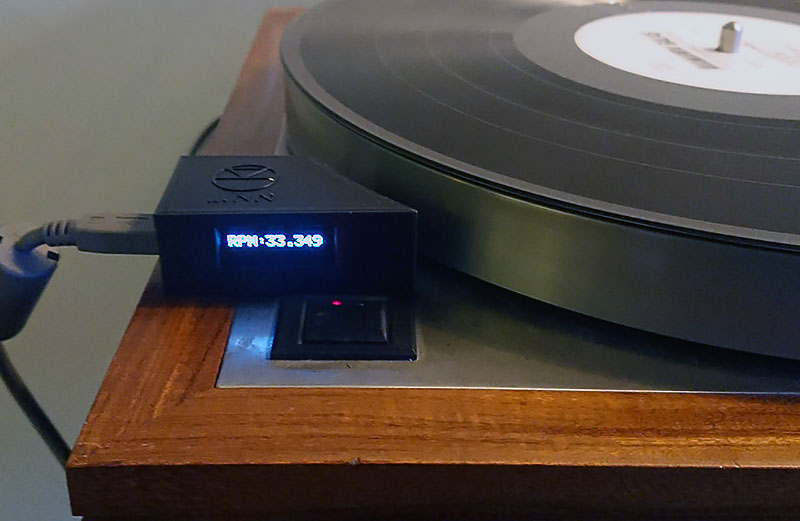
How to build the tiny handy TT tacho
The easy part, put the hardware together the shopping list first, and because you love it you buy the parts by following my links ;)
And if you end up building this tachometer please send me a picture of your version of it and I will post it on my website.
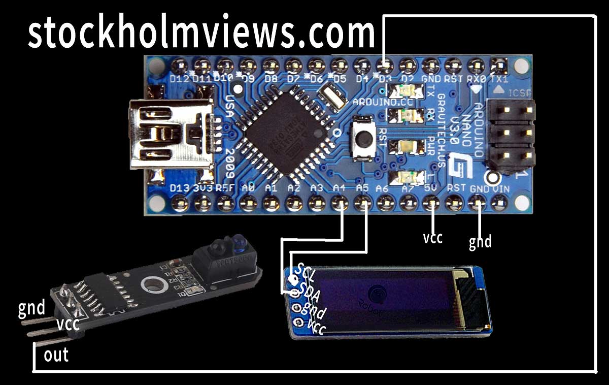
I use a Arduino Nano V3.0 since it tiny and easy to use.
The OLED display in the top image is a 128×64 version.
My final version will be using the smaller 128×32 version as I find it sufficient and will make up a neat unit. Make sure to get an i2c SSD1306 unit that will support the Adafruit SSD1306 library in the code. You can use any Arduino compatible display but then you will need to tweak the code and change to a display library that will work with your chosen display.
The sensor can be chosen by taste I have tested 4 different reflex and fork style sensors and all works just fine. The one I use in the pics above is this one. You will also need a USB power supply and a USB mini cable + the usual stuff like soldering iron hook up wire and beer.
Now when the shopping is done we can start putting the bits together, this is best described with an image.
Loading the Arduino Nano with software
The Arduino Nano will do nothing without some suitable instructions that will do the magic. If you not already have it is now time to download and install Arduino IDE it can be installed as a Windows 10 “App” but I suggest the stable installation version.
You will also need to get some additional libraries: Adafruit SD1306 V1.3.0 + Adafruit GFX Library V1.5.6 (Sketch/Include Library/Manage Library and then search and instal).
Set up the Arduino IDE by selecting the “Arduino Nano” (Tools/Board) and then select “ATmega328p Old bootloader” (Tools/Processor). now connect the Arduino Nano to your PC/MAC and hopefully you will find you Nano in (Tools/Port) if not search for drivers on the web and install as required.
Now load the sketch:
Connected and ready to hit Upload (The arrow in the top left corner of Arduino IDE, when loaded you will see the display coming alive. Now its time to test the sensor and see if it works. By slowly moving a stip of black paper or similar across the sensor you should get some readings.
Short movie showing my Linn LP12 spinning a bit to fast!
If the display does NOT come alive please download the i2c scanner here and upload it to your Arduino Nano, then while still connected with USB to you computer go to (In Arduino IDE) Tools/Serial monitor and look for address of i2c and change it in this section of the Tachometer sketch (row 37 in the IDE in my case) “if(!display.begin(SSD1306_SWITCHCAPVCC, 0x3C)) {“
The 0x3C is the address of my display and are quite common.
//* Uses I2C OLED interface.  SDA and SCL left most pins on 18pin header next to AREF
//* Check I2C address using Scanner example file; address range 0x20-0x27 and 0x38-0x3f.
//* RPM is computed using COUNT developed in Timer2 interupt @ 32µSec rate.
//* Timer0 is disabled so delay(), millis() and micros() will no longer function (hangs the UNO).
//* RPM calculation is: CALIBRATE/COUNT.  CALIBRATE=freq at digital pin 2 (PB2) x 120
//* At timer2 = 32.000 µSec, PB2 should be 15,625 Hz and CALIBRATE should be 1,875,000.
//* If AVERAGE=true, display data will be averaged MAX_AVG times. Pratical MAX_AVG values: 2-8
//* Set AVERAGE to false to disable averaging.
//* DO NOT average the data going to the PSU on serial port.

#include <Wire.h>
#include <Adafruit_GFX.h>
#include <Adafruit_SSD1306.h>
#define SCREEN_WIDTH 128 // OLED display width, in pixels
#define SCREEN_HEIGHT 32 // OLED display height, in pixels

#define OLED_RESET     4 // Reset pin # (or -1 if sharing Arduino reset pin)
Adafruit_SSD1306 display(SCREEN_WIDTH, SCREEN_HEIGHT, &Wire, OLED_RESET);

const int TRIGGER=3;            //* input on PB3
const float CALIBRATE=1873440;  //*equals freq @ PB2 x 120
const byte MAX_AVG=8;           //* set # of averages
const boolean AVERAGE=true;     //* set to false to disable averaging
unsigned int COUNT, RPM_COUNT=0;
unsigned long MSEC=0, ACTIVITY=0;
byte MS_PRESCALE=0, AVG_IDX=0, AVG_COUNT=0;
float RPM, AVG[MAX_AVG], TOTAL;
boolean UPDATE=false, DONE=true, STOPPED=true;

// the setup function runs once when you press reset or power the board
void setup() {
  Serial.begin(9600);
  pinMode(LED_BUILTIN, OUTPUT);
  pinMode(2,OUTPUT);                    //* Calibrate output
  pinMode(TRIGGER,INPUT_PULLUP);        //* PB3 trigger input
  // SSD1306_SWITCHCAPVCC = generate display voltage from 3.3V internally
  if(!display.begin(SSD1306_SWITCHCAPVCC, 0x3C)) { // Address 0x3C for 128x32
    Serial.println(F("SSD1306 allocation failed"));
    for(;;); // Don't proceed, loop forever
  }

  // Show initial display buffer contents on the screen --
  // the library initializes this with an Adafruit splash screen.
  display.display();
  delay(2000); // Pause for 2 seconds

  // Clear the buffer
  display.clearDisplay();
  display.setTextColor(WHITE);
  TCCR2A=0x02;    //* CTC mode
  TCCR2B=0x04;    //* ÷64 Prescalar
  TCNT2=0;
  OCR2A=7;        //* 32µSec rate
  TIMSK2=2;       //* enable OCR2A interrupts
  TIMSK0=0;       //* disable timer0 interrupts

  display.clearDisplay();
  display.setCursor(0,0);
  //display.print("Arduino Uno Tach");
  display.setTextSize(2);
  display.setCursor(0,5);
  display.print("RPM:--.---");
  display.display();
}
// the loop function runs over and over again forever
void loop()
  {
    if(UPDATE && DONE)
    { RPM=CALIBRATE/RPM_COUNT;      //* compute RPM
      if(RPM>28 && RPM<100)
      { Serial.print(RPM,3);        //* Dont average the serial data
        Serial.print('\n');
        Serial.print('\r');
        if(AVERAGE)                 //* check if we are averaging
        { AVG[AVG_IDX++]=RPM;       //* save current value in circular queue and move pointer
          if(AVG_IDX==MAX_AVG)      //* check for overflow
            AVG_IDX=0;              //* yes, reset pointer to beginning of queue
          if(AVG_COUNT==16)         //* Don't display average for at least 16 readings
          { TOTAL=0;
            for(int x=0; x<MAX_AVG; x++)  //* Recompute RPM as average of last MAX_AVG readings
              TOTAL+=AVG[x];
            RPM=TOTAL/MAX_AVG;
            digitalWrite(LED_BUILTIN,HIGH);
          }
          else
            AVG_COUNT++;            //* leave RPM as is, increment count
        }
        display.clearDisplay();
        display.setTextSize(2);
        display.setCursor(0,5);
        display.print("RPM:");
        display.setCursor(47,5);
        display.print(RPM,3);
        display.display();
      }
      DONE=false;                       //* reset trigger flag
      STOPPED=false;                    //* platter turning,reset flag
      ACTIVITY=MSEC;                    //* Start Activity timer
      display.setTextSize(1);
      display.setCursor(30,51);              //* display DISC Icon
      display.print(char(0));
      //display.display();
      mydelay(250);                     //* for at least 250mSec
    }
    if(!DONE)
      if(digitalRead(TRIGGER)==HIGH)    //* check for no trigger input
      { UPDATE=false;                   //*reset for interrupt routine
        DONE=true;
        display.setTextSize(2);
        display.setCursor(30,5);            //* turn off Icon
        display.write(byte(32));
        //display.display();
        mydelay(50);
      }
    if(!STOPPED)
      if(MSEC-ACTIVITY>2500)            //* check if platter stopped
      { STOPPED=true;
        display.clearDisplay();
        display.setTextSize(2);//* yes, flag it
        display.setCursor(0,5);             //* blank reading
        display.print("RPM:--.---");
        display.display();
        AVG_COUNT=0;                    //* reset average count
        digitalWrite(LED_BUILTIN,LOW);
      }
  }
void mydelay(int TIME)    //* range 1mSec to 65.535 Sec.
{
  for(int x=0; x<TIME; x++)
    delayMicroseconds(300);
}
//display
ISR(TIMER2_COMPA_vect)  //* timer 2 interrupt: 32µS rate 8 bit auto reload
{ COUNT++;
  digitalWrite(2,!digitalRead(2));    //* Toggle TP PB2
  if(digitalRead(TRIGGER)==LOW && !UPDATE)
  { RPM_COUNT=COUNT;                  //* capture value
    COUNT=0;                          //* reset counter
    UPDATE=true;                      //* flag for main routine
  }

  if(++MS_PRESCALE==31)               //* check for msec update
  { MS_PRESCALE=0;                    //* reset counter
    MSEC++;                           //* increment msec count
  }
}
There might be more soon…
I’m planning to make a wifi enabled version that can log the long term speed deviation to a web server running Grafana
Why you may ask?
For fun I will answer ;0)
A few quick reference tests shows?
The Arduino DIY above (Set to 8x average by reading to minimize erratic readings due to wow&flutter) it shows 33.333 / 33.334 constantly during the run of the below compared test methods a fairly steady result.
Using 50Hz led strobe android app and a printed PDF test strobe disk looks great speed-vice but not rock steady.
Laser RPM meter shows 33.3 (Only one decimal on my device “6234P+ Digital tachometer)
Android RPM Speed & Wow app shows 33.52
A bit of at least with my Sony XZ1 Compact, this app would be perfect if it supported hall sensor. (https://play.google.com/store/apps/details?id=com.AM.AM.RPMSpeed)
Android Magnetic Counter – RPM Meter = 33.2/33.4
This app was very good and feels like the “Real McCoy” due to use of a phone built in hall sensor, you only need a tiny magnet on the platter to get it working. However it could be improved with a few decimals to become a great turntable tuning tool. https://play.google.com/store/apps/details?id=lt.magneticcounter)
Android PlatterSpeed Dr Feickert, Mean frequency (30sec) 3152.6hz = 33,360 (MAX -0,30% – +0.33% wow and flutter) (Test record with a 3150hz tone required https://apkpure.com/platterspeed-vinyl-tool/ch.progtec.PlatterSpeed) This is the benchmark tool for many HiFi nerds ;) My advice: This app works even better if you make a direct connection with a 3.5 mm microphone cable between the phone and your phono amp (It also more neighbor friendly). In my case I had to put a 1k resistor between microphone + and ground to get it to work. gnd/mic rings may be different for other phones.
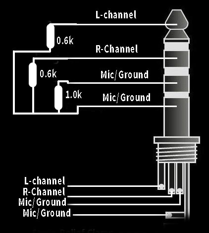
Platter speed direct conection for Android.
The 0.6k resistors will substitute headphones and the 1.0k resistor was what was needed to get the output from my phono amp to be read by my Android phone. No luck for IOS friends since Apple have rules that makes it just noth worth the hassle to Dr Feickert
IOS Turtabulator = 33.38 Works with IOS about the same as the once for Android but are not free and have less features.
Phones used iPhone 5c / Sony XZ1 Compact both resting on a sponge ballanced in the center of TT platter.
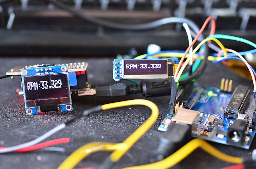
The above left display are hooked up to a Arduino Nano V3 and the one to the right is connected to a Arduino UNO both cards are feed from a digital waveform generator with a 0.556hz square wave. Both cards shows a steady (steady like frozen!) 33.329 vs 33.339 when the frequency changes they follow each other (variation is negligible, +- .001 in variation at room temperature). Maybe I will look in to coding a calibration funktion ;0)
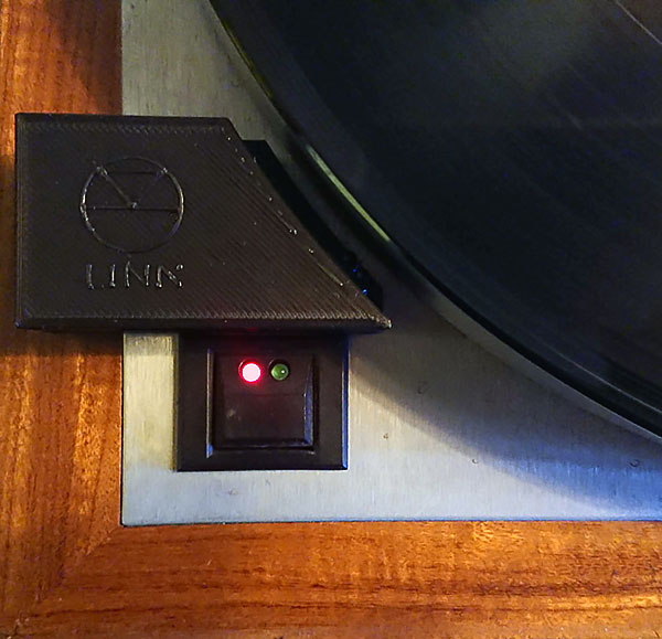
3D Printed cover.
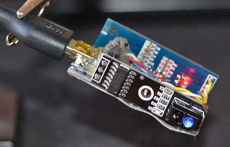
The cover is now designed to house the OLED display, Arduino Nano and the IR reflex interrupt sensor (Small blue things near the pointy part of the enclosure). The design has a radius side with the sensor that follows the radius of my Linn LP12 platter. I’m a rookie on 3D printing and CAD so bear with me if the quality of the enclosure in the picture isn’t perfect, the logo in particular is hard to get nicely printed. This project is open source so I will publish my print files for anyone to tweak.
Download STL:
Download F360:
Download G-code:
Further enclosure Ideas includes.
1. Simple display bezel for the display for if you like to build a turntable integrated version.
2. A version with built in small rechargeable battery for about 30-60min operational time to get rid of the bulky mini USB.
3. A version with a fixed “super slim” USB cable that can be hidden in the narrow space between TT top plate and platter.
4. Looking forward to your thoughts ;)
Some more pics below.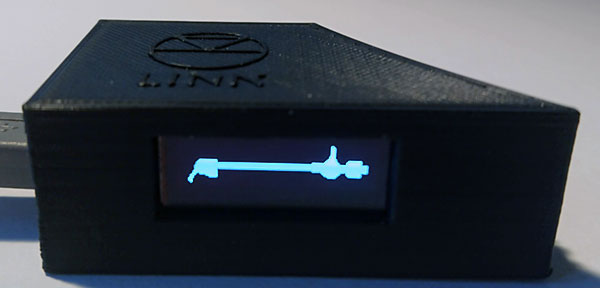
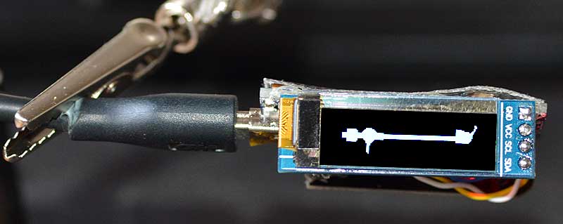
Boot up splash screen.
If you want this splash screen then you need to modify the splash.h file in the Adafruit_SSD1306 library (Click to download link to the NAIM ARO arm splash.h file).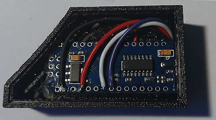
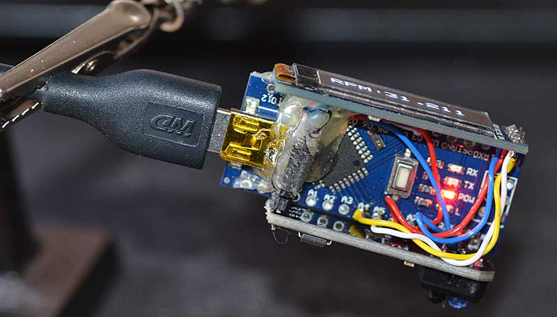
Arduino nano inside the 3D printed box.
The board need to be trimmed a bit in the corner
facing the curved part of the box be careful to avoid
damaging the pcb.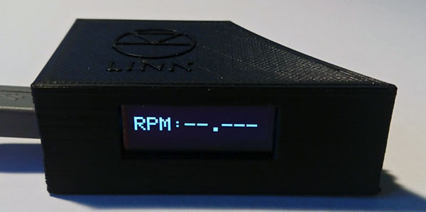
Display show no rotation sensed or speed out of range.
Temporary installed.
A thin 2 wire usb power only cable can be wired directly to the Arduino Nano board and the be routed under the platter to be hidden, that will also allow us to close the lid with the tachometer in place :D
Bom:
Arduino nano
OLED Display 0.92 inch 32x124px
IR interrupt sensor
USB charger and USB mini cable of your taste.
Other display/sensor may work but those are the one I used.
3D Printer: I went for the Creality Ender 3 Pro, this is the first one I used and for the priced asked the quality is fantastic!
Notes&advices
- Use a flat black strip on the edge of your TT platter (Works on my linn LP12 standard flat silvery platter) try a reflex strip if your platter is black and report back to me so I can spread the word.
- Try different width of the strip and distance between the sensor and platter for best performance/reliability.
Next:
Data output for the upcoming motor controller is definitely in the pipeline!
Maybee also make it WIFI an/or data logging capable if that would be something asked for ;)
This might be multi version project!
1.Portable version with rechargeable battery.
2. Portable version powered by USB power supply.
3. Installation version, fixed sensor wired stand alone meter.
4. Installation version, fixed sensor unit to build in to TT.
5. As 3&4 + signal output for upcoming TT motor controller.
6.?
Just ask :D