
I just wanted a cheap magnetic drill press to be able to do some occasional jobs because some times ju just can’t fit the bits in to your regular drill press. However soon I felt that it would be nice to be able to regulate the speed (rpm) and also be able to back out a tap in case of tapping work.
So lets get on with it, my victim for this modification is a Vevor MD40 but the same drill is sold under many different brand names and they will all be the same I guess!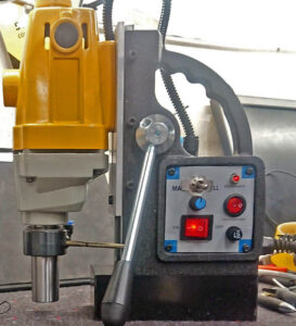
This picture shows the mod completed with the original control panel hacked by a savage ;-)
Parts list will be posted at the end of this article.
Schematics for the MAG Drill reversing modification
Surfing the www gave me some hints and I came up with this schematic draft.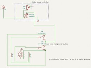
OK, here comes the disclaimer take it seriously!
I will not take any responsibility for any kind of damage or electrocuting so if you are unfamiliar with high voltage wiring or at any stage of this modification description please don’t continue you may put your self in danger!
MD40 Mag drill tear down for modifications
I will not in detail describe how to do this because it is a very easy work and if you read the disclaimer then you also know that if you can’t take it apart then you should probably bail out of this mod!
This is how it looks in pieces :D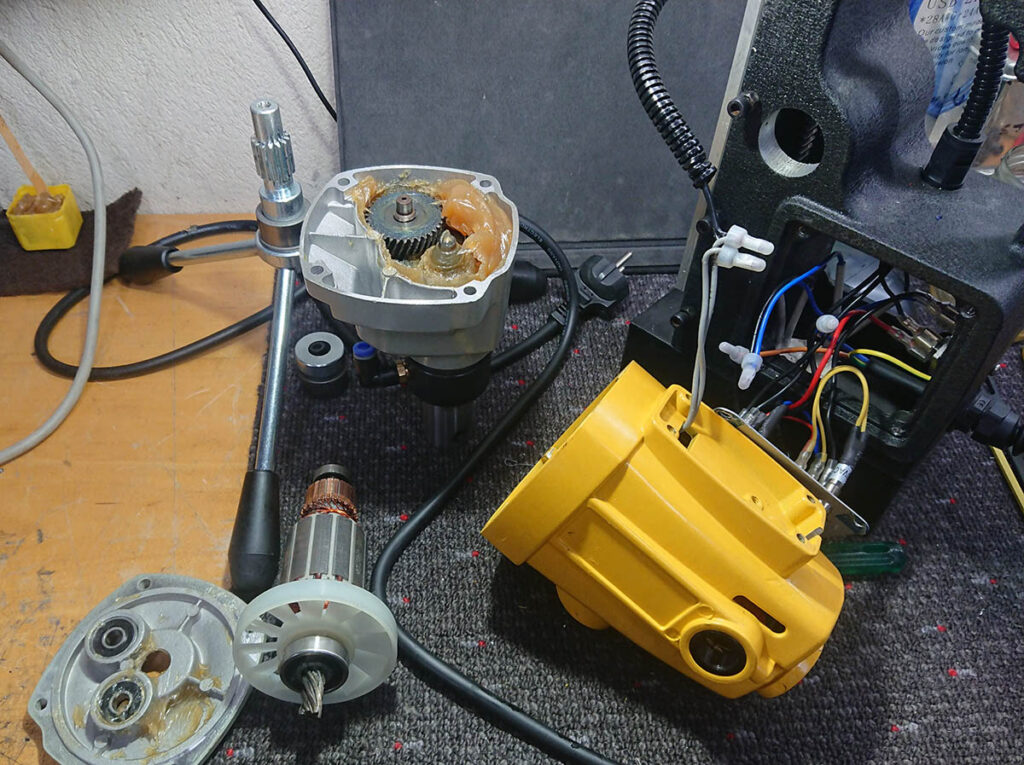
Remove the handle assembly to be able to access the screws to remove the drilling head from the stand.
Then simply remove the four screws holding the head together and carefully rip it apart haha…
Use a spatula to remove but save some of the grease to prevent to get the sticky stuff all over your workbench.
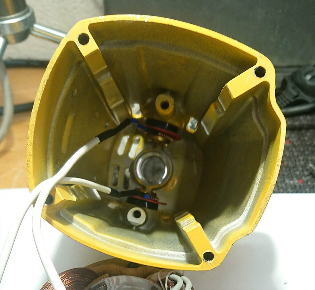
Now we have the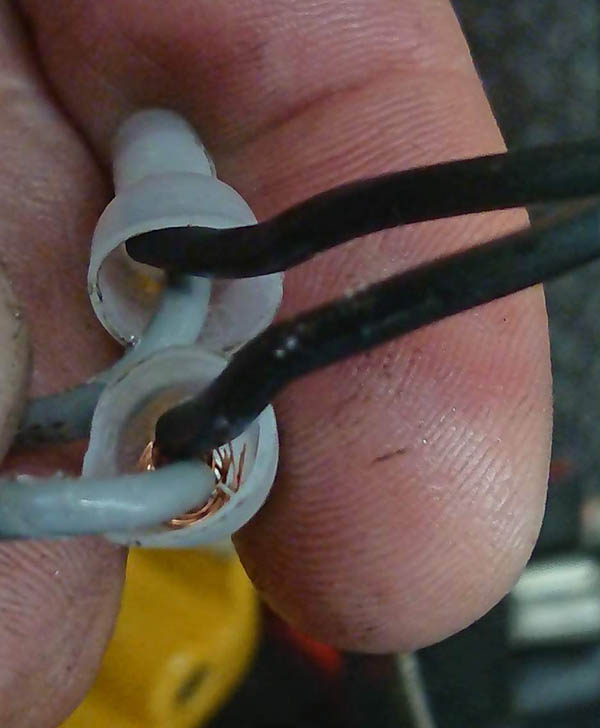 opportunity to do some QC inspections and then I revealed this….. I guess this machine would have been necessary to put on surgery sooner or later anyway!
Separating stator and rotor windings
To be able to switch the rotation direction on a universal motor we have to wire the stator and rotor in separate and then connect them in different configurations with a 2 pole 3 position switch FWD-OFF-REV
or if you like CV-OFF-CCV as per schematics.
Stator mod
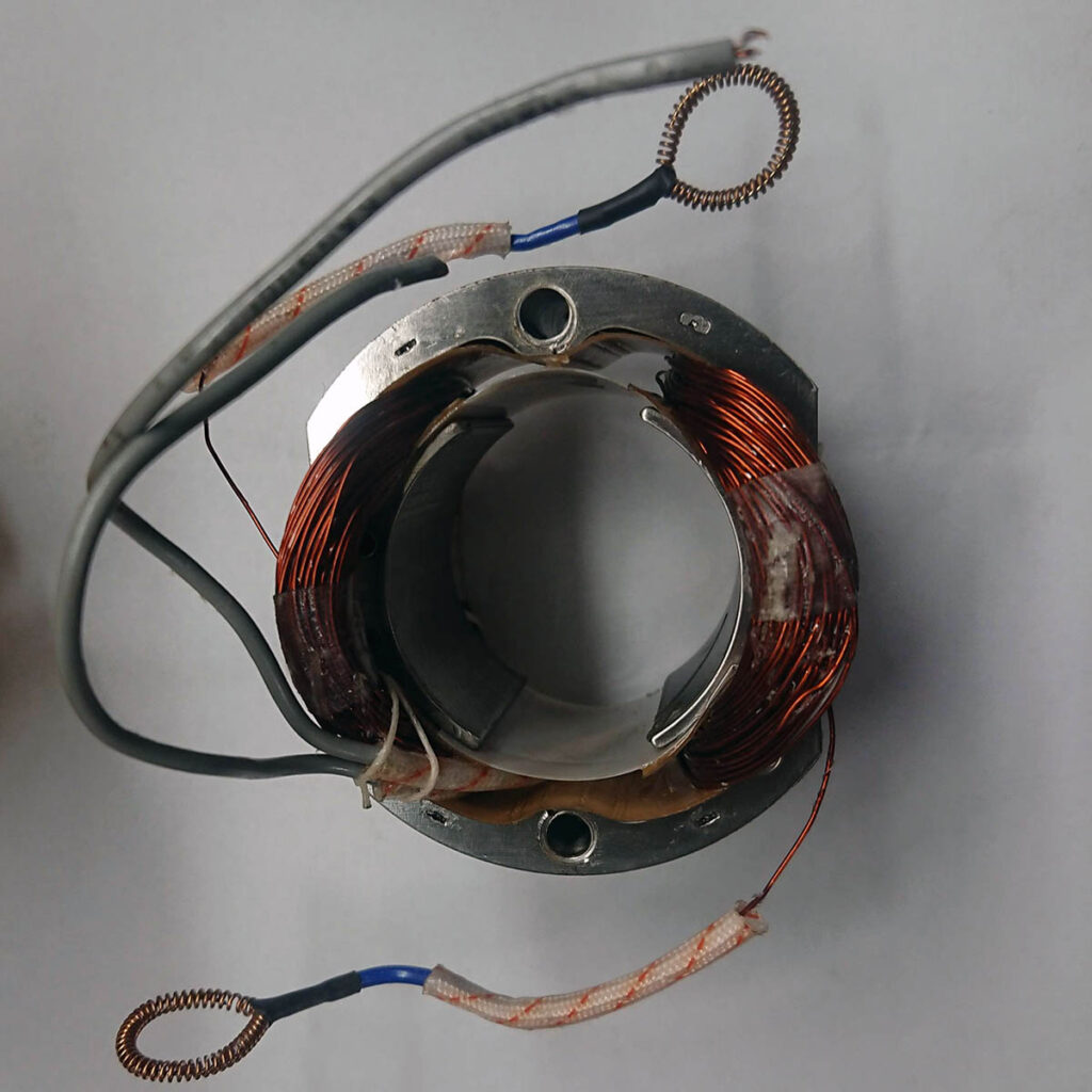
Above pic: The stator in original shape. The spring loops are the connector for the brushes, slide away the high temp insulation sleeves and cut of the loop wires by the junctions and put them aside.
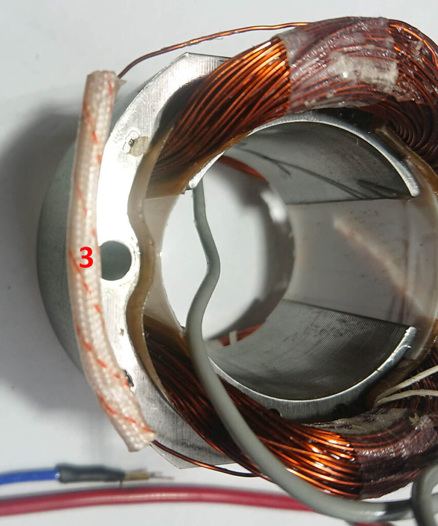
Now connect the two stator windings together I would suggest that you are using a crimping method because this part might get hot enough to melt a solder joint. Use some high temp insulation to cover the crimp splice (Think safety and do this as a pro). You will also need to extend the insulated wires (gray on this sample) to be able to rout them all the way back trough the flexible conduit and to the control panel.
Now crimp some extension wires to the spring loop connectors for the brushes, use a generous length to avoid to run short of wire you can trim it at a later stage. I used som wire that I had on hand but this wire was unnecessary bulky and hard to pull trough the flex conduit. Access for re install of the spring loops are kind of narrow and might require so patience ;) Now its time to put everything together again and that is exactly like tearing it down but in reverse. Now you have two more wires to pull through the flex conduit it might help with some soap as lubrication.
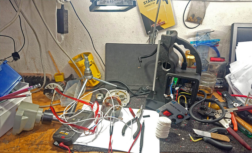
And remember to keep your work bench tidy………
Note: I used some cotton lace to lock the spliced stator winding part in place se if you can find it in the picture :D
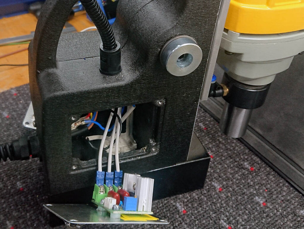
The speed controller is a common type that can be found at the usual places all over the www.
3 wires to hook up (terminal has 4 but two of them are connected together) plus a connector for the potentiometer that controls the speed. The blue square component in the foreground are a multi turn potentiometer that you use to adjust the speed range for the control potentiometer with and the adjustment depends on your machine so that is a “adjust by feel trial and error thing”. This board is mounted on the specifications back cover plate, make sure to get proper electrical insulation distances!
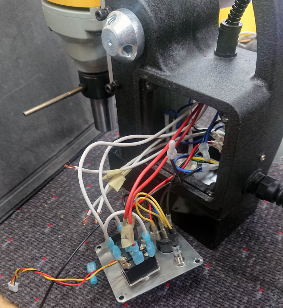
Wiring the control panel. The small connector with red,black, yellow wires is for the speed knob (potentiometer). The three unconnected white wires are coming from the speed control board.
Now just follow the schematics….
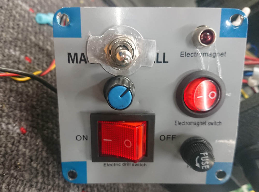
I might one day make a pretty panel but for now I need to run to the next project haha….
Notes
The motor on this particular magnetic drill press MD40 was never intended for running counter clock vice so when doing so at full speed it will arc at the brushes quite wildly and this will not be or feel very nice.
However if you turn the speed down the arcing will decrease and at a point stop doing so for me this is acceptable because the main purpose with reversing a mag drill is for backing out the tap after taping a hole and then I want to keep the RPM down anyway. After all this is a cheapskate mag drill mod so I’m kind of satisfied!
Parts list
You also need some flat connectors for the switches and forks for the speed control board plus som extension wiring but I guess that you already have that in your drawers if you intend this mod ;)
Stay safe not connected…….